Wurlitzer 4500 electronics repairs
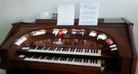
The Wurlitzer had a few problems when I got it: the lower keyboard didn't play, half the console lamps didn't light up, and some of the pedals did not play. The organ also had a bit of a 60 Hz hum. I've tackled all of these problems!
Lower Amplifier
Re-capping
Once I got the organ home and opened it up, it was pretty easy to see why the lower keyboard didn't play -- the lower amplifier was unplugged. And once I plugged it and turned the organ on, it was pretty easy to see why it had been unplugged -- there was a very loud 60 Hz hum and hardly any other sound output from the amplifier. The main culprit was a bad power supply filter capacitor in the amplifier.

A little searching online revealed that this is a common problem. Electrolytic capacitors have an aqueous electrolyte in them, and in the 1960s they were sealed with rubber. After fifty years or so, it's common for that rubber to degrade and allow the electrolyte to dry out, at which point the capacitor no longer functions. The usual solution is a complete "re-capping" of the organ, replacing all of the original electrolytic capacitors with new ones. (I suppose one could replace just the failed ones, but all of the old ones are prone to failure, so you might as well do them all at once.)
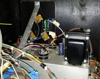
So, that's what I did with the lower amplifier. It turned out to be more work than I expected, for a few reasons! First, the large filter capacitors were chassis mount packages, and actually had three or four capacitors in each package. The amplifiers used lots of point-to-point wiring with other components soldered to the terminals of the capacitors, mostly power resistors. Replacing them with modern through-hole capacitors required finding places to mount the new capacitors themselves as well as those other components. Smaller electrolytic capacitors mounted on the circuit board were much easier to deal with, and it was really interesting to see how much smaller new capacitors are compared to fifty-year-old ones with the same ratings. Despite the smaller size I still had trouble finding space for the new filter caps, so you can see them in the photo at right poking up through the holes that held the original capacitors. They're just to the left of the transformer.
Power amplifier replacement
After replacing the capacitors I was able to finally power up the organ with the lower amplifier plugged in, and I discovered another problem. With the amplifier plugged in, there was an almighty THUMP each time the organ was powered up. Measuring the output of the amplifier revealed a constant DC offset of more than a volt. A little DC offset on an amplifier's output is to be expected but that much is really not good, because it is an additional constant load on the amplifier and speakers.
The output stage of the amplifier was coupled through a transformer, so because the transformer can't pass DC the offset must have come from the output stage itself. I spent some time ... too much time ... adjusting and swapping out bias resistors for the output stage, and it never made very much difference to the DC offset. Eventually I had to admit defeat. Either something was wrong with one of the output transistors as well or I didn't understand the circuit as well as I thought. (The latter is not unlikely; I've been an electronics hobbyist for a long time but there is a lot that I don't know, especially regarding analog circuits.) So, I made the decision to just replace the output stage of the amplifier with a modern one.
I have several LM3886 audio amplifier chips mounted on circuit boards that implement their recommended application circuit, left over from another project that never quite got done. (That project was a high-powered hifi amp, but I'm no longer at a place in my life where blasting loud music is likely to happen!) The LM3886 would replace the output, driver, and pre-driver stages of the original amplifier; the pre-amp and swell control stages would be kept. Those earlier stages look like they're responsible for shaping the audio signal to some extent and do something with signals to and from the Spectratone and other filter circuits, so I wanted to just leave them alone so as to not interfere with the organ's sound or function. The later stages, that I would replace, should be purely about amplification, so replacing them with a modern power amp with low distortion could only help.
The power amp replacement was complicated by the fact that the amplifier supplies a few different voltages to different loads, and none of those supplies are regulated. For example, the pre-amp runs on a nominal 15V and draws about 13 mA. That power is supplied from a 21V supply through a resistor whose value is selected to drop the voltage by the required 6V, and then a big filter cap is added to the 15V supply. The 21V supply is derived in the same way from a 31V supply, which is derived from the +35V rail. All this means that if I remove a load from the 31V supply (like the driver stage of the amplifier), it will throw off all of the other voltages and the amplifier probably won't work correctly!
I determined from the schematics that my power amp replacement would eliminate the need for the 31V supply entirely and leave only pretty small loads on the 15V and 21V supplies. So, I installed two LM317 voltage regulators with the appropriate resistors and capacitors to make regulated 15V and 21V supplies from the +35V rail. After that I was able to cut out everything from the original amplifier circuit from the pre-driver on. I reduced the capacitance on the output of the swell control stage so that it would settle more quickly at power-on and then wired that to the input of the LM3886 circuit.
The LM3886, with its interface board, I mounted to the main heat sink; you can see it in the photo above near the center of the photo. Wiring up the power and audio input was straightforward. The input to the power amp goes through a transient when the organ turns on and takes a second or two to settle, so I needed to have the LM3886 delay turning on to avoid popping from that power-on transient. So, I made an RC circuit between ground and the negative rail, and connected that to the mute input of the LM3886 through a 15V zener diode. That startup circuit mutes the amplifier for a couple of seconds at power-on, preventing any popping. You might have noticed in the photos that the original transistors of the power amplifier are still on the heat sink. At the time I was working on this power supply, I wasn't sure how much work I would end up doing on the organ, so I tried to leave all the original components in place, even if not connected, so that if some future owner wanted to restore the amplifier completely to its original state they could do so. With the work I've done since that is no longer a concern, so if I ever return to this amplifier to do more work I'll go ahead and remove those components.
Console lamps
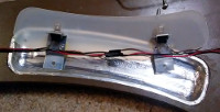
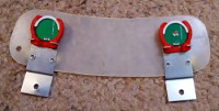
The console has several lamps above the stop tabs that illuminates them, wired in two parallel strings of six lamps. One of the strings had a burnt out bulb, so it wouldn't light. I didn't have any replacement bulbs that would fit, but I do have a bunch of white LEDs on small PCBs -- leftovers from a product idea that didn't take off -- that would just about fit in their place. I 3D printed holders for the LED boards that fit in the brackets where the incandescent lamps were previously, then installed them and wired the LEDs together in the same way the incandescent lamps were.
The original lamps were powered from line voltage through a transformer, which would not work for LEDs that want direct current! I removed the transformer and then installed a socket on the lower amplifier and matching plug on the cable for the lamps, so they now draw DC from the amplifier's positive rail. A resistor inside the amplifier's chassis limits their current draw.
One wrinkle with these lamps that I didn't appreciate at first is that the lamps themselves, in their cutouts in the top of the console, are actually located just behind the vertical wall of the front of the console. That way they don't shine directly on the console; only the light that is scattered off of the shiny walls makes it out, thus producing a diffuse light. I didn't notice that and angled the LEDs to point straight downwards, so most of their light goes right into the top of the wall of the console. Enough does make it out to illuminate it, it's just not ideal.
Upper Amplifier
The upper amplifier did not have any problems when I got the organ, but it did contain lots of fifty-year-old electrolytic capacitors that would need replacement sooner or later. So I decided to give it the same treatment as the lower amplifier, replacing the original electrolytic capacitors and also the power amplifier. (The upper amplifier had also developed a DC offset on its output, though not nearly as bad as the lower amplifier's had been.)
This took a while. The upper amplifier itself is more complex than the lower one, since it also handles vibrato and reverb, and it also powers more other components such as the tone generators and the pedal latch circuits. I ended up adding four LM317 voltage regulators, to provide 13.6V (vibrato oscillator), 16.5V (preamp and swell control), 23V (reverb), and 27.5V (PSM). The reverb circuit is connected between the swell control and pre-driver stages of the amplifier, so I decided I had better leave the pre-driver stage in place this time. I did change the resistor values in that stage so that it would run on the 16.5V supply and provide a smaller voltage gain of only 10. Once I was done with this amplifier, the 60Hz hum was entirely from the organ!
I gave the LM3886 on this amplifier a mute circuit similar to the one on the lower amplifier, but it isn't entirely successful. It works fine on power-on, but when I turn the organ off there's a bit of a snap. I think what's happening is that the positive rail on this amplifier is loaded much more heavily than the negative rail, mostly due to the tone generators. So the positive rail voltage drops off very quickly and throws the input to the power amplifier out of whack, well before the negative supply decays enough to cut off current from the mute circuit and mute the amp.
I still haven't entirely re-capped this amplifier; the original capacitors for the ~200V supply are still in place because I neglected to get replacements for them, and I just discovered another electrolytic capacitor hiding down in one corner. Those will get replaced one of these days, though.


Comments
RSS feed for comments to this post