Moon Buggy 1.0 - construction
This article describes the construction of version 1.0 of Moon Buggy. This was the not-quite-working version I entered in the 2006 Baltimore Kinetic Sculpture Race. This page runs in chronological order, not necessarily any sort of logical progression.
I started construction in February of 2006. This was later than I would have liked, and of course everything took longer to do than expected. What it added up to was that as race day approached I focused more on what I could put together quickly, not necessarily what would work well. I ended up throwing parts of the sculpture together at the last minute and didn't really properly test it all. On race day we spent a lot of time broken-down and trying to come up with clever fixes to get the sculpture moving. In the end we got through about a third of the race, which I suppose isn't too terrible. And afterwards I was able to fix up the problem areas and put in a good showing in the Columbia Festival of the Arts' parade.
February 26, 2006:


I started by machining the hubs and sprockets for the wheels. At right is one of the hubs with machined sprocket:
The sprockets came with a plain bore, shown at right.
The center cylinder of the hub has bearings pressed into it, which support the whole wheel on the axle. The wheels will be constructed with a foam core and fiberglass skin; the disks on either end of the hub are there so that the skin will have plenty of surface area to adhere to to transmit load and torque. I used screws to attach the disks (and the sprocket) to the center cylinder, you can see the mounting holes in the sprocket in the top photo. It would have been more robust to weld the aluminum parts together, however I don't have a welder and wouldn't trust the strength of my welds anyway.
This was the most machining I've ever done, before this I'd only made some small bits in college, five years ago), so it took most of the month to remember how to use a lathe.
Over the course of this project I generally get my materials and machine components from McMaster-Carr and MSC Industrial Supply, two big online distributors of, well, stuff. The foam and fiberglass-related material came from US Composites and random other hardware came from local hardware stores.
April 10, 2006:

(Long gap here, where I forgot to take any photos. Dang!)
Here is the first wheel, already completed. At the center you can see one of the disks of the hub. There's a bit of tape over the bearing seat at the middle to keep the resin out. The core of the wheel is made of 2pcf density polyurethane foam. Over that is a skin of fiberglass cloth and polyester resin. I used more layers of fiberglass near the center of the wheel (where the stress will be higher), which is why the wheel has a darker color there.
I can't believe I didn't take any photos of this wheel in progress! It was quite an adventure. I tried to use a kiddie pool as the mold for the wheel. Unfortunately the bottom of the pool wasn't flat and the foam didn't self-level as I expected it to. I had to use lots of extra foam to make the wheel oversized and then cut it down to the proper shape. I made a rig that let me mount the wheel sideways and spin it around so I could trim off the extra foam and get thing to be wheel-shaped. It was a mess! My roommates Jeff and Andrea, who actually parked their cars in the garage before I took it over, were very understanding.

Because the polyurethane foam was so much trouble, for the left wheel I tried expanded polystyrene foam instead. That's the pink house insulating foam you see at the hardware store. I bonded several layers together to get to the desired 10” thickness of the wheel. Then I cut a hole through the middle for the hub and bonded it into place. With the hub in place I could put the wheel up onto my rig again to trim it into a circle. Happily, this stuff didn't make nearly as much of a mess as the first wheel.
April 18, 2006:

For the first wheel I just draped a couple of layers of fiberglass onto the core and brushed the resin on. I expect the polystyrene core of this second wheel to be weaker, so I wanted to take more care with the skin, whose strength will be more important. At the same time, I don't want the skin to be any heavier than necessary. So, I decided to try vacuum bagging. This was the first time I tried this technique in about six years and on a much larger scale than what I'd done before. The basic idea is that, after you wrap your part in fiberglass and slop on the epoxy, you put it into an airtight bag with some padding and hook it up to a vacuum pump. Once there's a vacuum inside the bag, the atmospheric pressure outside pushes the fiberglass tight against the part and squeezes any extra epoxy out into the padding.
In this case, by the time I had applied the fiberglass, set up the vacuum bag, and found most of the leaks, the epoxy was already curing. I never did find all the leaks, so I wasn't able to pull a decent vacuum. What this meant for the wheel is that it is probably heavier than it has to be (because the extra epoxy wasn't squeezed out), and the skin is lumpy and funny-looking.
April 20, 2006:

In the end, both wheels have held up fine. Here they both are, with tires applied as well. The tire material is just adhesive-backed polyethylene foam, cut into strips and pressed onto the wheels. Funny thing, the adhesive held pretty well when we tested the vehicle (both on land and in a swimming pool), but on race day the tires fell off almost as soon as I rolled into the inner harbor. There's something in the water that just ate right through the adhesive. I wouldn't recommend swimming there ...
For the 2007 race I added some additional strips of foam that held the tires in place.
Just as for the first wheel, the second wheel's color changes with the thickness of the skin's thickness. Where it is thin the pink color of the foam comes through and where the skin is thicker the yellow color of the epoxy dominates.


April 23, 2006:
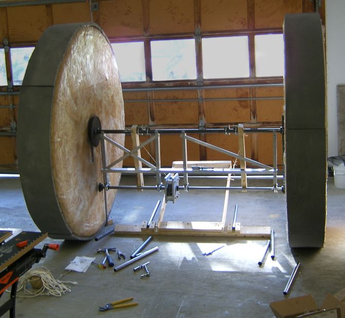
With the race just two weeks away, I finally started building the structure of the moon buggy. Here's how it looked at the beginning of the day: this is first time I had the wheels mounted to the axle.
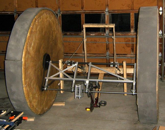
By the end of the day I had the structure mocked up, which looked like this:
The wooden rectangle under my back will become the frame for the seat-back. The bars set up in front of the axle are the two halves of the driveshaft, and the metal box in the middle of them is a sort of differential. Below is a later close-up of the differential. The chain on its left side goes to a crank I can reach with my hands. By holding it still or spinning it one way or the other I can force one half of the driveshaft to turn relative to the other, by virtue of the different gear ratios within the differential.

April 28, 2006:
A few days later I had some of the real frame completed. The frame for the driveshaft is complete and the driveshafts and differential are mounted. Some of the seat mockup became part of the real sculpture. I used telescoping tubes to connect the seat to the rest of the frame, so that I could raise it up above the waterline for the water portion of the race. The tubes are partly mounted in the photo below, you can see them hanging off the bottom member of the seat frame.

April 29, 2006:
By the next day I had the seat mounted and the rest of the drivetrain (a hacked-up bicycle) mounted.
The only piece of the bicycle frame that I kept was the bottom part that normally runs between the crank and the rear wheel. I had to flip it upside down and backwards to make it fit into the sculpture. I was rather surprised that this worked without any serious problems -- there were even mounting holes for the rear dérailleur on the opposite side of the frame. I had to drop the front dérailleur though, as there was no longer a frame member to attach it to.

May 2, 2006:
This was the Tuesday before the race and I had just installed the brake, a first (unsuccessful) attempt at a mount for the steering crank, and the seat. When the sculpture is empty the center of gravity shifts so that the seat tips up vertical, but when riding I lie on my back on that blue canvas. The brake consists of the disk on the right driveshaft (left side in this photo) with a set of bicycle brake calipers gripping it. The gear ratio between the driveshaft and wheel is such that the single brake caliper should have more braking power than it would on a bicycle. On the other hand, a bicycle has two of them and is considerably lighter -- so Moon Buggy has some trouble stopping sometimes!

May 3, 2006:
And here we have the vehicle as it looked when it made it's first test-drive. The brake handle and shifter is now mounted. The steering crank has padded handles and is chained to the gearbox.